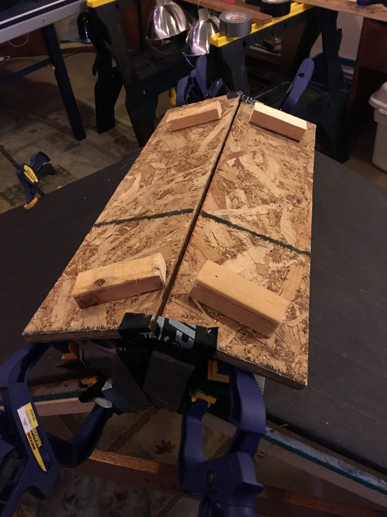
So far, I have performed wingnut testing on PSA tapes and on basement waterproofing products. Very recently, I started working on wingnut testing of roof venting, using an easel made from 2-by lumber and two sandwich panels of 1/2-inch OSB (see the photo above). The easel includes a vent space and ridge vent between the two panels. Each sandwich panel is made up of two layers of OSB, with an air space between the two layers. The easel demo simulates one vented cathedral roof cavity facing one direction and the other facing 180 degrees in the opposite direction.
Frankly, the reason I chose to try to simulate cathedral soffit-to-ridge venting is because it was the easiest to build as an “easel.”
Caveats
Keep in mind that this is wingnut testing. Some caveats:
- I am assuming that this simple easel mimics larger actual roofs.
- I have just gotten started on this testing; there is a lot to work out, and changes will be based on early results. Initial test results are likely to lead to changes in the test protocol; I will be looking for input on the initial approach from many in the building and roofing industry, including ridge vent manufacturers.
- So far I have only tested three ridge vents; there are quite a few more out there.
- I am not releasing the names of the manufacturers of the two ridge vents I have tested because I don’t understand yet why the results are so different, and so far I have not had both of the manufacturers review my test and the results. It only seems fair to take this cautious approach even though it may be way less gratifying to readers of this blog.
Stay tuned; more testing and identification of tested ridge vents soon to follow.
Some background on roof venting
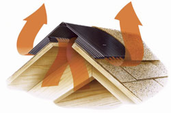
It was Bill Rose and his book “Water in Buildings” that really turned me into a building science wingnut, with a desire to conduct tests in the same vein. (For more on Bill Rose, see this blog by Martin Holladay.) Bill and his book encourage all of us to question building maxims, such as the 1:150 and 1:300 roof venting rules. (For more on attic venting, see “All About Attic Venting.”)
But what about all those arrows in roof ventilation diagrams that sometimes depict air flow? Some of these diagrams are appealing and some others that seem a lot more creative — or maybe even wishful.
We know that to get air flow through a ventilation channel, we need three things:
- A hole
- Another hole
- A driving force
For driving forces, we have three as well:
- Stack effect
- Wind
- Mechanical (fans)
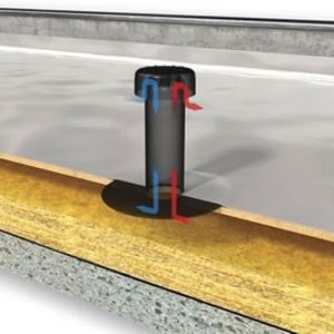
We will leave mechanically driven air flow (or fan-assisted venting) off on its own for the time being (although there is a lot of GBA content regarding powered roof vents, including “Fans in the Attic”). That leaves us to imagine (or maybe even track) just how wind and stack effect create air flow within roof venting systems.
But boy, there are a lot of variables to consider: the type of venting in attics (soffit-to-ridge or gable-to-gable), the impact of roof pitch, the depth of the vent space, the type and color of roof cladding, the temperatures driving stack effect, the direction and intensity of wind, etc.
Wingnut approach to soffit-to-ridge vent testing in cathedral roof assemblies
For the last ten years or so, I have been a presenter at the Better Buildings Better Business (B4) conference in the Wisconsin Dells, Wisconsin. It’s a great conference. This year I had three educational sessions on attics and roofs: “Building Science and the Codes”; “Roofs and Attics That Work”; and “Roofs and Attics That Don’t Work.”
The B4 crowd seems to appreciate and even like building science wingnut testing, so I rigged up what I thought was a decent demo of roof venting and sent this diagram to the conference planner, John Viner, as well as some roofing experts at GAF.
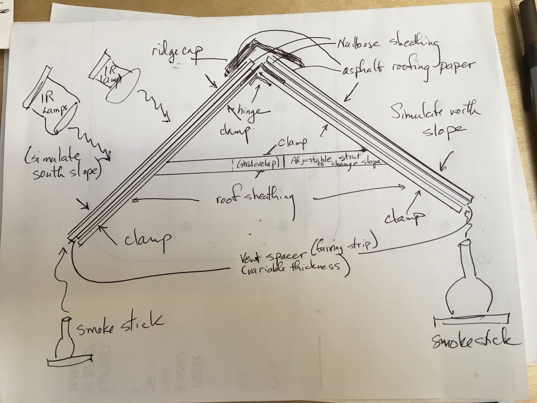
The setup allowed me to pretty easily change:
- Roof vent space depth (3/8”, 3/4”, 1”, 1.5”, 2”);
- Roof pitch (18/12, 12/12, 5/12, 3/12);
- Type of ridge vent;
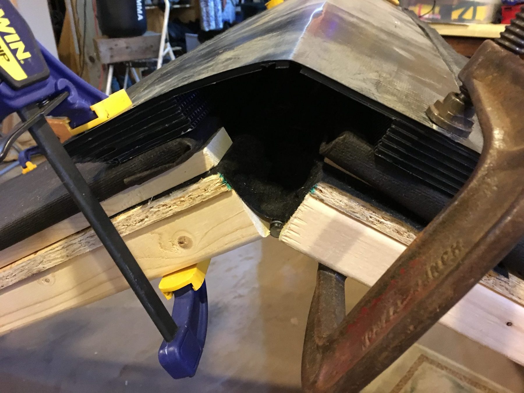
- The driving forces (stack effect driven by “solar heating” — actually, infrared heat lamps — on one side of the A-frame roof).
I tested two manufactured ridge vents and a home-made ridge cap. The home-made ridge cap consisted of a totally open vent slot capped by a mini-roof made of OSB, with each side of the mini-roof measuring 6 inches wide, and with 1-inch-thick wood block spacers under the OSB to establish a 1-inch-high vent space in the ridge — the same depth as the roof slope vent space depth.
The test consists of:
- Heating up the “south” side of the demo roof with two 250-watt infrared lamps (augmented with a hair dryer as needed) until the surface reaches around 90°F to 100°F;
- Measuring the temperature of the “roof” surface with a digital infrared thermometer;
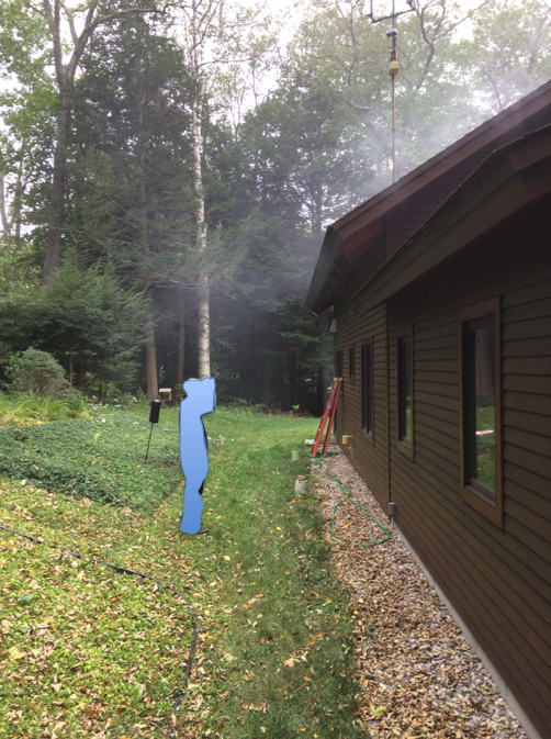
- A smoke stick test involving a timer (to determine how long it takes the smoke to vent out).
Because of the time crunch getting this test ready for the B4 conference, the tests below are largely qualitative; subsequent testing under more controlled conditions will result in more consistent heated roof temperatures and accurate timing for smoke emergence.
Initial results in my basement
Working by myself, I did not at first figure out how to position the lamps, record the surface temperature, and operate the smoke stick. So there is no video of my first test, which was conducted with the easel at a 18/12 pitch, with a 1-inch vent space, and with a manufactured ridge vent.
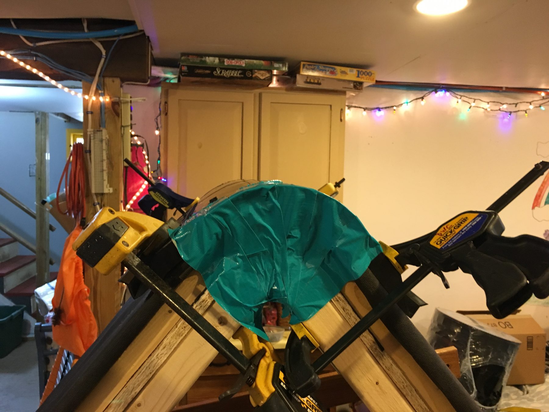
You will have to take my word for it: the smoke only came out at the bottom of the opposite roof slope. No smoke came out the manufactured ridge vent at all. What? (If you can’t take my word for it, take a look at the second of the three videos on this page.)
Because of this result, I then made up and tested the completely open homemade ridge vent (2). Smoke quickly and readily came out the top of the opposite slope, but not the heated side — another unexpected result. (See the youtube video below.)
Building-Wright Wingnut Ridge Vent testing homemade ridge vent 2 3:12 pitch, 1-inch vent space
On to B4 testing
At the B4 conference, we did WTF (Wingnut Test Facility) roof venting testing at the end of each of the three sessions. As happened in my basement testing, Ridge Vent 1 resulted in no smoke coming out the ridge vent but plenty rolling out the bottom of the opposite side of the roof easel (see the video below).
Building-Wright Wingnut Ridge Vent #1, 12:12 pitch, 1-inch vent space
In the video above, you can see a hair dryer being used to augment (speed up) the heating of the “south” side of the demo roof. My initial plan was to use the hair dryer to simulate a different driving force for roof venting — wind — but we ran out of time before we could demonstrate that driving force.
Next, we switched out the ridge vent to another manufactured roof vent (one which I did not have in my basement but that a major roof product manufacturer exhibiting at B4 provided), and this ridge vent worked well — pretty much like the typical arrows depict. I will call this vent Ridge Vent 3 (see the youtube video below).
Building-Wright Wingnut Ridge Vent test #3; 12:12 pitch, 1-inch vent space
The results from my basement testing and the testing at the B4 conference were very similar.
- Ridge Vent 1 — a popular manufactured ridge vent — did not have any smoke exiting the ridge; instead, smoke rolled out the bottom of the opposite side.
- Ridge Vent 3 — another popular manufactured ridge vent — had smoke readily exiting the ridge vent, pretty much as depicted in Image #1.
- The unobstructed homemade ridge vent (Ridge Vent 2) had most of the smoke rolling out of the ridge vent on the opposite side.
- Cutting away the insect screening “gauze” on Ridge Vent 1 did very little if anything to improve the lack of smoke exiting at the ridge vent.
- Slope matters; the steeper the slope, the faster the smoke moved out of the roof assembly.
- The depth of the vent space matters; the deeper the vent space, the faster the smoke moved out of the roof assembly.
NOTE: I taped off the ends of the ridge vent in the demo so that air and smoke did not escape from these unintended openings (see image below).
Onward
It sure looks as though we need to learn a lot more about how the arrows should really be drawn for soffit-to-ridge vented cathedral roof assemblies.
I don’t know why the two manufactured roof vents performed so differently and I hope to work with ridge vent manufacturers to better understand why.
I am looking forward to more roof vent testing. I think my initial basement tests and B4 conference tests should inspire more work, particularly:
- Testing more manufactured ridge vents.
- Being more exacting with how much heat is applied and the resulting temperature of the heated roof slope.
- Measuring actual times for each of the tests between smoke starting in at the bottom of the assembly (at the “soffit” or “eave”) and wherever the smoke exits.
Stay tuned for more results in my next GBA blog, and feel free to weigh in with your own insights — and maybe even your own wingnut testing.