It has been a while since I blogged about my first round of Wingnut roof vent testing, so here is a reminder of the questions that the tests should answer:
- Does soffit-to-ridge cathedral roof air flow actually follow the nice neat arrows that ridge vent manufacturers show in their brochures?
- Does the configuration of a manufactured ridge vent make a difference in venting effectiveness?
- Does vent channel depth (the code requires a minimum depth of 1 inch) or roof pitch make a difference in air flow rates?
- What’s the difference in effectiveness between wind-driven ventilation and stack-effect-driven ventilation?
The hiatus in publishing this blog sequel was mainly due to the fact that I had to work out a better approach to generating smoke, to make the testing more realistic at the “eave” and “ridge.” I also had to work out a way to test wind-driven venting. But as you will see below, all of these “improvements” mostly served to convince me that I need to field-verify the findings from my indoor Wingnut testing.
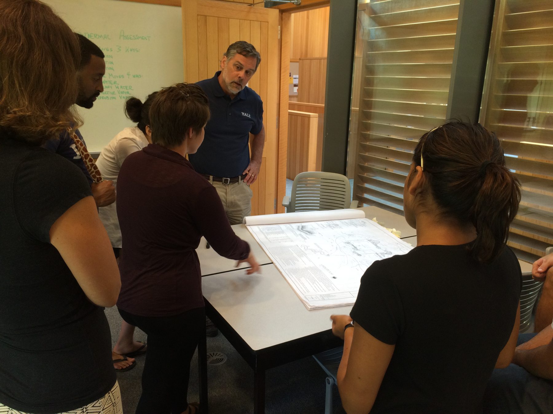
The pressure was on, because about two months ago I committed to running a round of Wingnut roof vent testing for a local meeting, the Building Science Guild meeting of the Sustainable Energy Outreach Network (SEON) in late April 2019.
Changes to the test rig and test protocol
Here are the changes I made:
1. I bought a theatrical fogger to replace my handheld smoke sticks; see the photo at the top of the page. (There is a wide range of cost between different brands of foggers. Since I could not afford the “Cadillac” model — the Retrotec Tiny S, at $950 — I settled on a Chauvet DJ Hurricane 1000 for $120.)
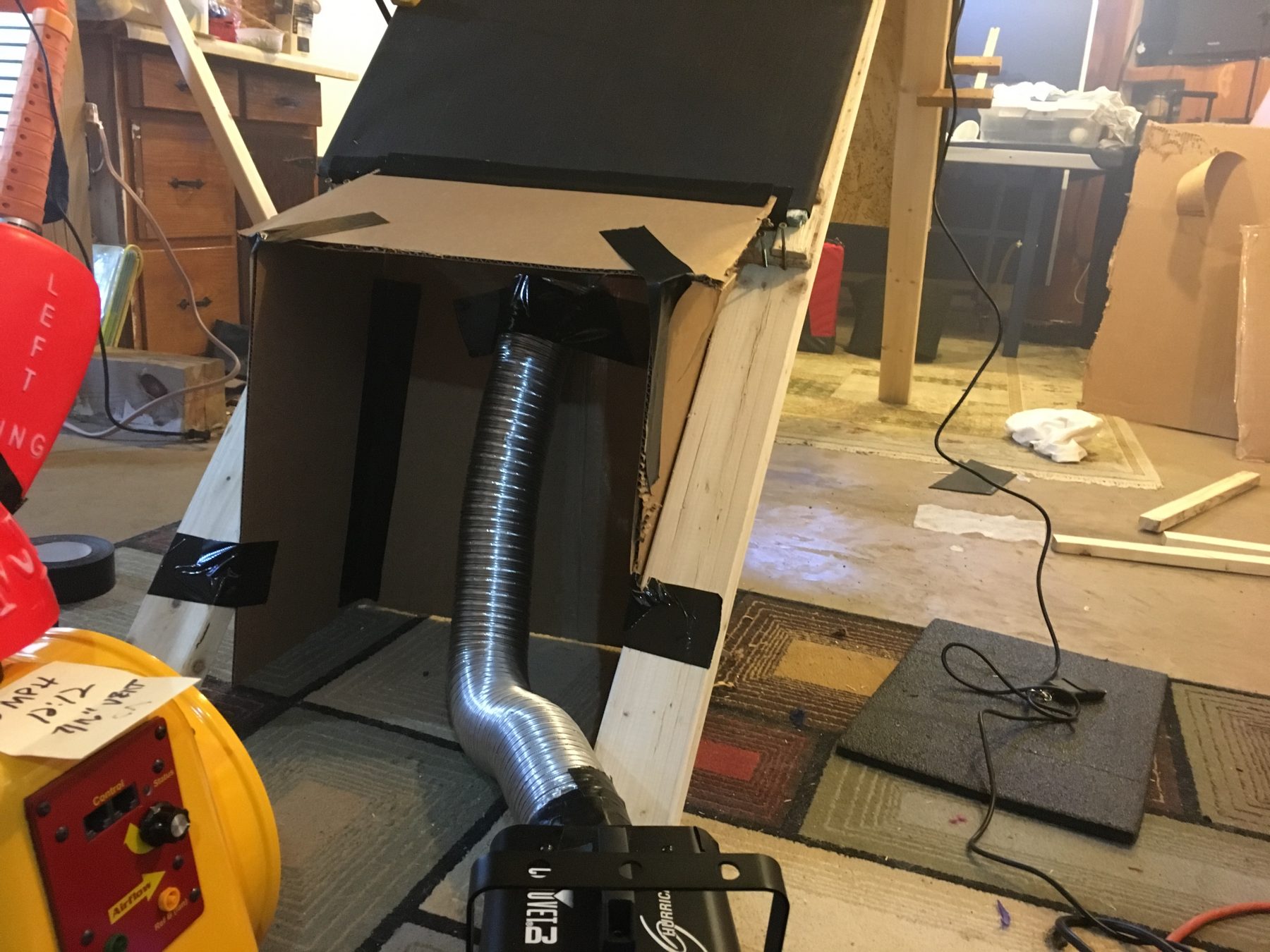
2. I built a cardboard eave “wall” and soffit/overhang; see the photo above.
4. I used my Duct Blaster during testing to simulate wind-driven venting.
A quick note about types of roof ridge vents
There are, of course, a slew of different roof ridge vents (see photo below). I certainly have not tested all, or even most, of them, but I am can break them down into two types: those with vertical-leg baffles that extend well beyond the ridge cap shingles and those without the extended baffles.
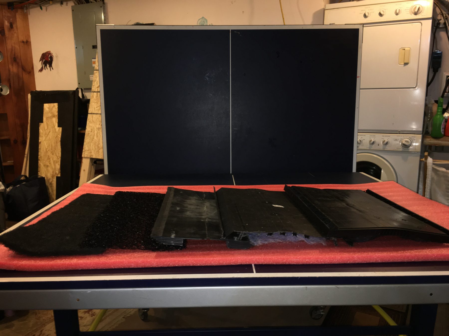
I am making this distinction because ridge vent manufacturers of the former style claim that the vertical-leg baffle is key to enhancing vent flow driven by wind.
Round 2 testing results
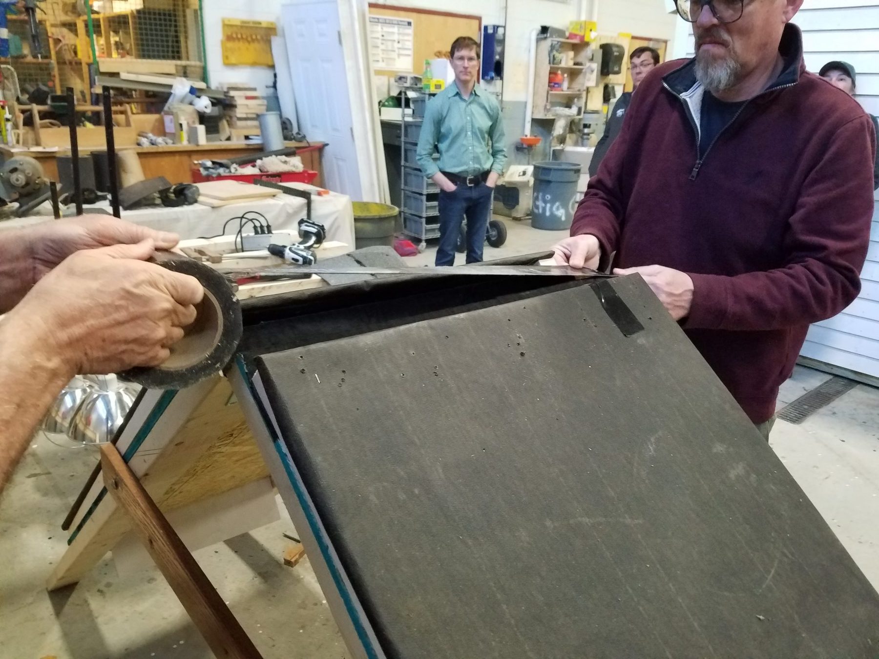
We set up the Wingnut roof vent test rig in the wood shop of the Windham Regional Career Center. (Instructor John DiMatteo is an active member of the Sustainable Energy Outreach Network guild).
- The first test was a roof assembly with a 3:12 pitch and a 1-inch-high vent space, tested for both stack-effect flow (simulated by heating the roofing with infrared heat lamps) and wind-driven flow (simulated with a Duct Blaster). See the photo at the top of the page, as well as this YouTube video: https://youtu.be/njbhE9xH_Kc [Video credit: Alan Benoit, architect].
With a low slope, the type of vent or the type of driving force doesn’t matter much. With this low of a slope, there is just not very significant vent flow at the ridge. We do get evidence of vent flow down and out the bottom of the opposite side from the driving forces (wind and stack effect).
- The second test was a roof assembly with a 10:12 pitch, a vertical-leg baffle type vent, a 1-inch vent space, and with stack effect as the driving force; see this YouTube video: https://youtu.be/g61yRGjRWMc [Video credit: Jon Saccoccio, architect].
Pitch makes a big difference, with much more flow from both sides of the ridge vent and much less down and out the opposite slope.
- The third test was a roof assembly with 10:12 pitch, a 1-inch-deep vent space, stack effect venting, but with a non-vertical leg ridge vent; see this YouTube video: https://www.youtube.com/watch?v=yDag6Xh1VwU [Video credit: Jon Saccoccio, architect].
We get pretty good vent flow up and out the ridge vent but still quite a bit of flow down and out the other slope.
- The fourth test was a roof assembly with a 10:12 pitch, a 1-inch-deep ventilation space, wind effect ventilation, and a vertical leg ridge vent; see this YouTube video: https://www.youtube.com/watch?v=h6vsNLBehBo [Video credit: Jon Saccoccio, architect].
We finally get vent flow at the ridge very similar to the arrows most manufacturers show. And note the difference that occurs when we focus the wind effect up on the roof deck as opposed to all the turbulence created when wind hits the “eave” wall and soffit as well. We discovered how hard it is to measure the wind speed along the roof slope; pretty much all we know is that we got the wind pretty similar among our wind-driven tests (with the handheld anemometer reading 3 to 4 miles per hour). - The fifth test was a roof assembly with a 10:12 pitch, 1-inch-deep ventilation space, wind effect venting, with a non-vertical leg ridge vent; see this YouTube video: https://www.youtube.com/watch?v=akOStDJ1wB8 [Video credit: Jon Saccoccio, architect].
For whatever reason, the non-vertical leg ridge vent configuration is significantly different from the vertical leg baffle ridge vent. There seems to be much more resistance at the soffit vent opening, and much less air flow, with the non-vertical leg ridge vent.
What’s next?
Everyone at the Building Science Guild meeting agreed: while the “benchtop” A-frame testing rig has been helpful in teasing out some understanding of the factors that affect soffit-to-ridge vent flow in cathedral roof assemblies, we need to field-verify the indoor testing.
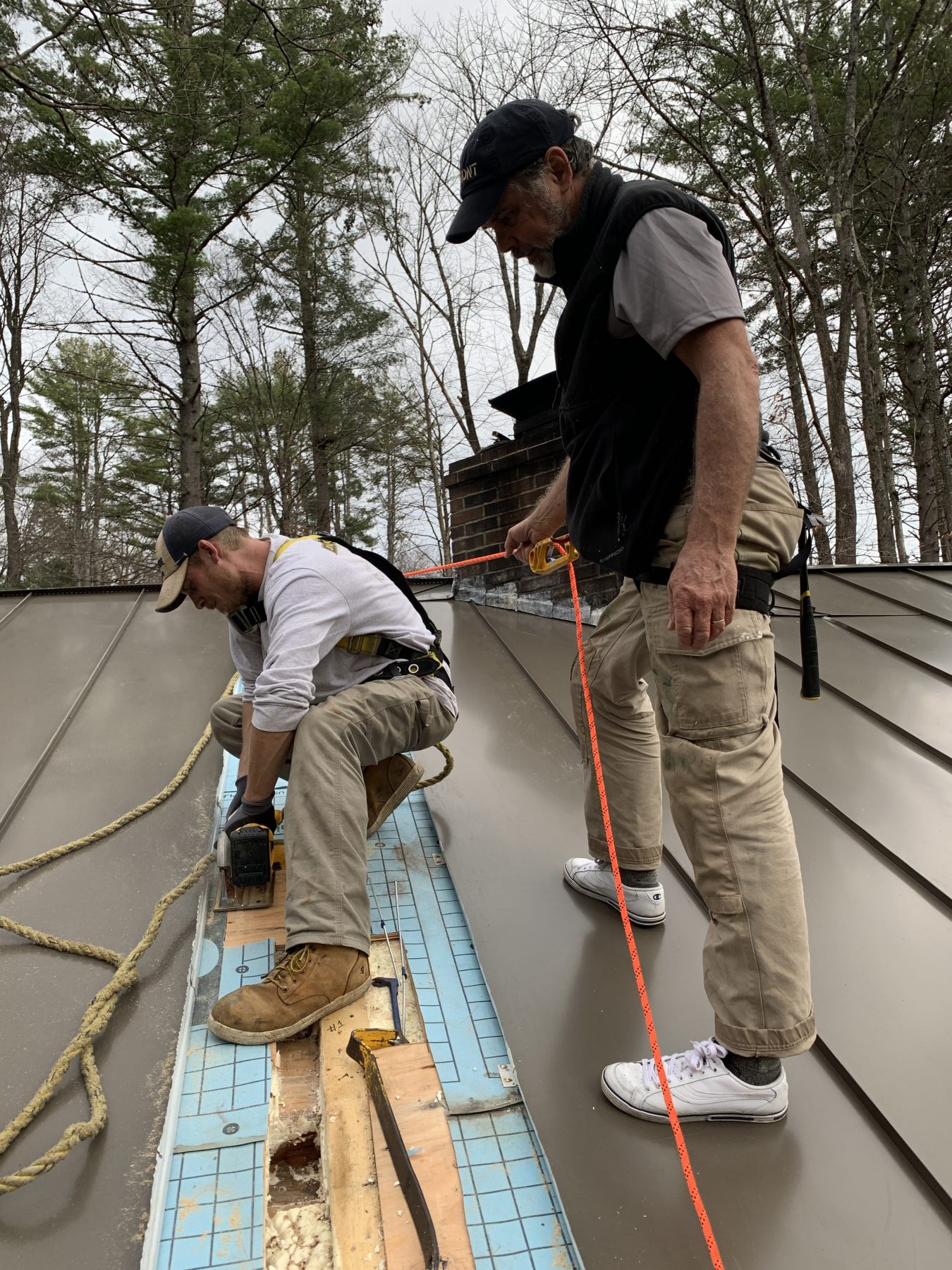
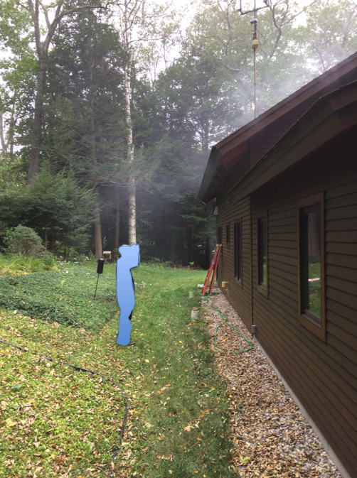
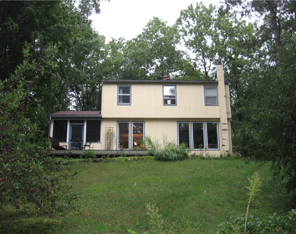
So I am hitting the road with my theatrical fogger and a good sturdy extension ladder to a slew of colleagues’ buildings to test soffit-to-ridge cathedral roof assembly air flows in the field, documenting the following conditions while assessing vent flow:
- Outdoor temperature
- Solar condition: sunny, partly cloudy, etc.
- Roof pitch
- Roof cladding (roofing material)
- Type of soffit vent
- Type of ridge vent
- Wind speed at roof eave above and below the soffit and at the ridge (if I can get to the ridge).
Stay tuned for another round of Wingnut ridge vent testing, this time with videos from the field.
Call to action
You too can be a Wingnut: use the information just above to do your own fieldwork on soffit-t0-ridge vent testing on cathedral roof assemblies and report your results back here in the Comments section of this blog. Together, we can figure this out quite a bit faster than would be possible with just one Wingnut.